|
|||||||||||||||||||

Advanced vectorization optionsAdvanced vectorization options can be customized through the Vector|Options menu.
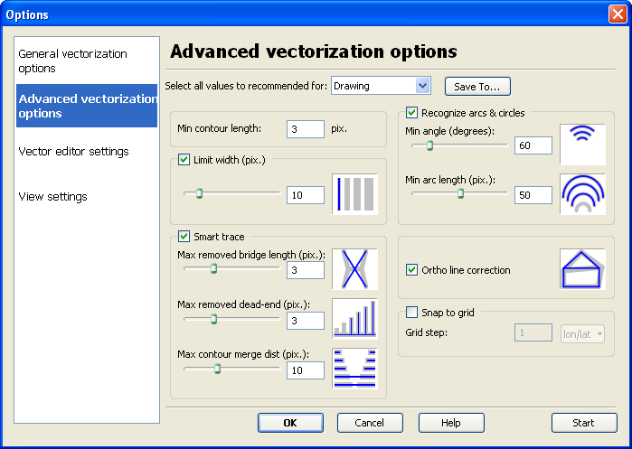
Image typeSelection of predefined parameters set. You can define and save your own set ofparametres by "Save To" button. Min contour length (pixels) removes short contoursMin contour length - all contours that are shorter than the length you have entered will be removed. The length units are in pixels.
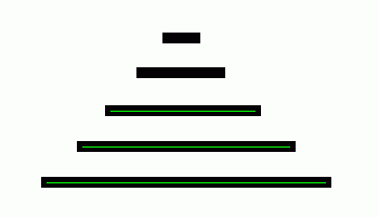
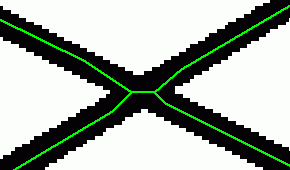
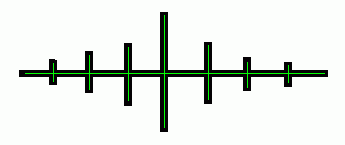
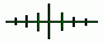
Smart trace - polyline tracing settingsVextractor can trace polylines through intersection with an heuristic algorithm. There are three settings that affect that algorithm's results: maximum length of "bridges" to be removed, maximum length of "dead-ends" to be removed and size of gaps to be filled. Max removed bridge length (pixels) is the maximum length of bridge between two neighboring polyline intersections. Such bridges will be deleted and the remaining polyline ends will be drawn together.
Max removed dead-end (pixels) is the maximum length of contours' dead-end branches that are to be removed.
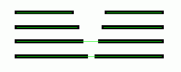
Max contour merge dist (pixels) - maximum size of gaps to be removed (in pixels).
Here are a few important notes related to processing order to be used in the Smart Trace mode, which describes the application of various vectorization settings. The first step of the procedure consists of tracing contours through intersections. This step is affected by the Max removed bridge length, and Max removed dead-and settings. The second step of the procedure is filling the gap between contours. The maximum length of gaps to be filled is defined by the Max contour merge dist setting. The third step is deleting the short contours that are shorter than Min contour length. Recognize Arcs and CirclesThis option allows the program to recognize arcs and circles. The recognition quality depends on the following two settings: Min angle (degrees) prevents the program from drawing redundant fake arcs on contours with insufficient curvature. Min arc length (pixels) lets the program cut short arcs.
Ortho Line Correction Enables the orthogonal line recognition mode. Snap to Grid [on/off] and Grid step (in current units) This option is used for aligning vector data by the grid with the step you specify in current units. |